Using the Breadboard
Overview
Teaching: 30 min
Exercises: 10 minQuestions
What is a breadboard?
How are a breadboard’s conductors organized?
How can you use a breadboard to connect devices to the Arduino?
Objectives
Understand how sockets are connected on a breadboard.
Understand how to program pins on an Arduino for OUTPUT.
Use Pulse Width Modulation to simulate an analog OUTPUT.
Let’s go back to the blink program we started with – or you can continue with the sketch as you modified in the previous episode.
Code Reuse:
Get used to starting with working code and adapting it to new purposes. It’s much easier to begin with something that does part of what you want and simply revising or extending it to do what you want.
You can either create a new sketch, but you can also go the parent directory that contains the folder with your blink sketch and copy the whole directory. Then rename the sketch inside to match the new name.
$ cd ..
$ cp -r blink blink-two
$ cd blink-two
$ mv blink.ino blink-two.ino
If you compile and upload the new sketch, the built-in LED should blink according to the pattern of the previous sketch.
void setup() {
  pinMode(LED_BUILTIN, OUTPUT);
}

void loop() {
  digitalWrite(LED_BUILTIN, HIGH);
  delay(500);
  digitalWrite(LED_BUILTIN, LOW);
  delay(500);
}
Replace LED_BUILTIN in the sketch above with 13. The built-in LED on the board is wired to pin 13 on the Arduino. Note that the LED continues to blink after compiling and uploading the sketch.
Next we will attach an LED on the breadboard to pin 13.
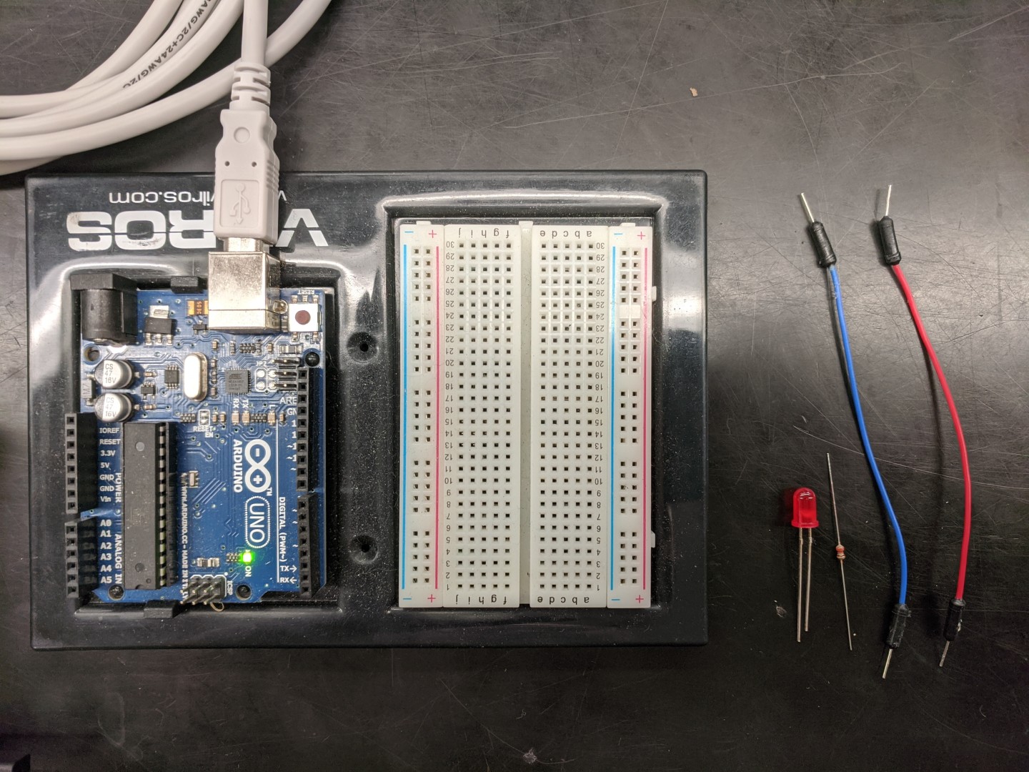
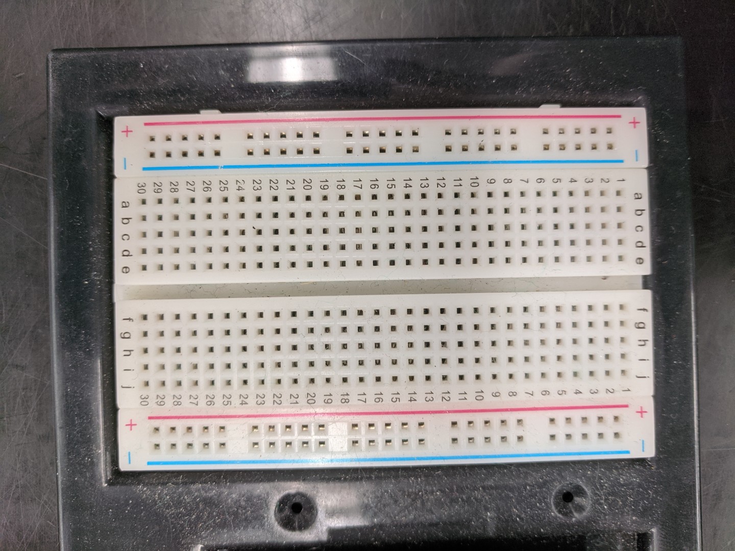
A breadboard has conductive elements that allow you connect components together using jumpers – small wires with connectors at each end. The typical breadboard that comes with an Arduino kit has two halves The red and blue lines represent conductors that run the length of the board. The other conductors run horizontally toward the middle, but don’t connect across the middle.
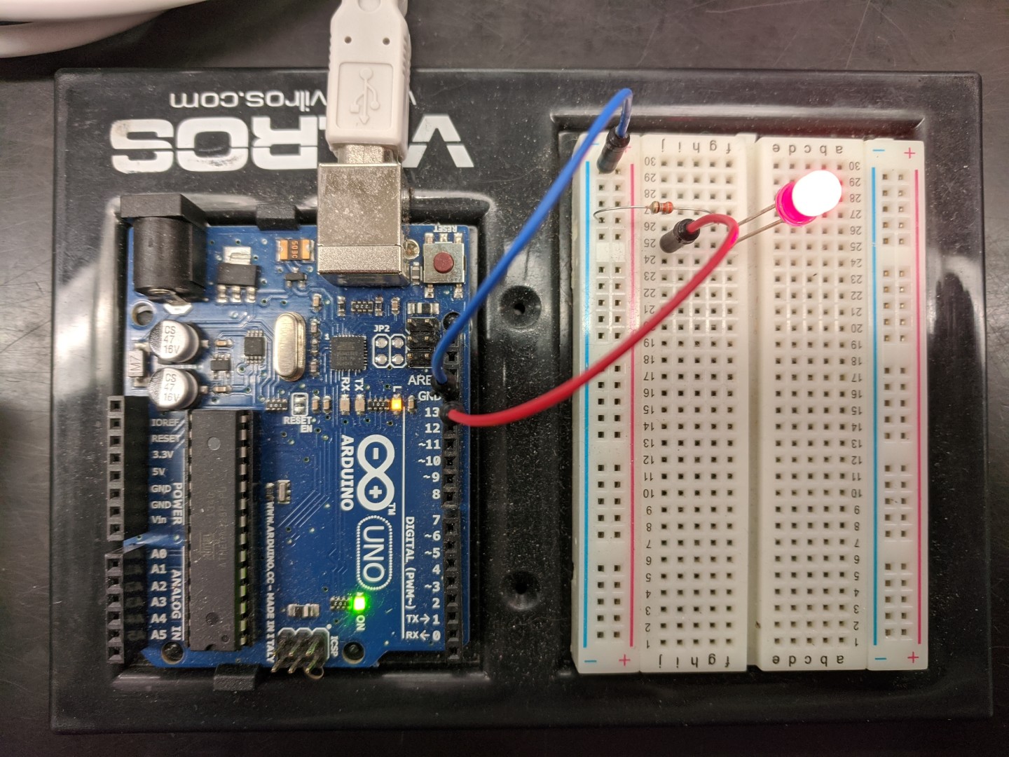
Place the LED so that its two connectors are attached to adjacent conductors on the breadboard (separate horizontal lines). Note that the two leads on the LED are different lengths. The longer lead is the one that should be connected to pin 13. Place a jumper from another socket on the breadboard and connect it to pin 13. But to complete the circuit, we need to connect the other lead to ground.
If you connect a jumper from one of the ground pins on the Arduino to the lengthwise conductor next to the blue line, we can use that to ground any of the circuits we build on the breadboard.
Finally, LEDs only need a tiny amount of electricity to light up and can be damaged by running too much electricity through them. For this reason, we will complete the circuit by using a resistor. In this case, we’ll use a 330ohm resistor. Put one end of the resistor in the same row of conductors as the short lead on the LED and the other end in the grounded conductor. If all of your connections are correct, the LED on the breadboard should blink at the same time as the built-in LED.
For portability, you can define a variable you can set to represent the pin you’re using to light the LED. Then you only need to one change to switch to a different pin.
Try this:
Try moving the positive connection to the LED to pin 6 and define a variable to represent that pin in all of the places where it is referenced.
Digital pins (and LEDS) are either off or on, but some digital pins (e.g. 3, 5, 6, 9, 10 and 11) can simulate analog OUTPUT through pulse width modulation (PWM): that is, they can rapidly turn on and off so that the proportion of the time the pin is HIGH can be varied.
int led=6;
void setup() {
  pinMode(led, OUTPUT);
}

void loop() {
  // gradually increase time pin is HIGH
  for(int i=0; i<255; i++){
    analogWrite(led, i);
    delay(5);
  }
  // gradually decrease time pin is HIGH
  for(int i=255; i>0; i--){
    analogWrite(led, i);
    delay(5);
  }
}
Try this:
Try moving the positive connection to the LED to pin 6 and define a variable to represent that pin in all of the places where it is referenced.
Key Points
Breadboards allow for complex, temporary connections.
Pins can be turned ON or OFF.
Pulse Width Modulation turns pins on and off really fast.