Introduction
Overview
Teaching: 15 min
Exercises: 10 minQuestions
What is the Arduino platform?
Why do we use the Arduino platform?
Objectives
Understand what Arduinos can do.
Understand when Arduinos are a good choice.
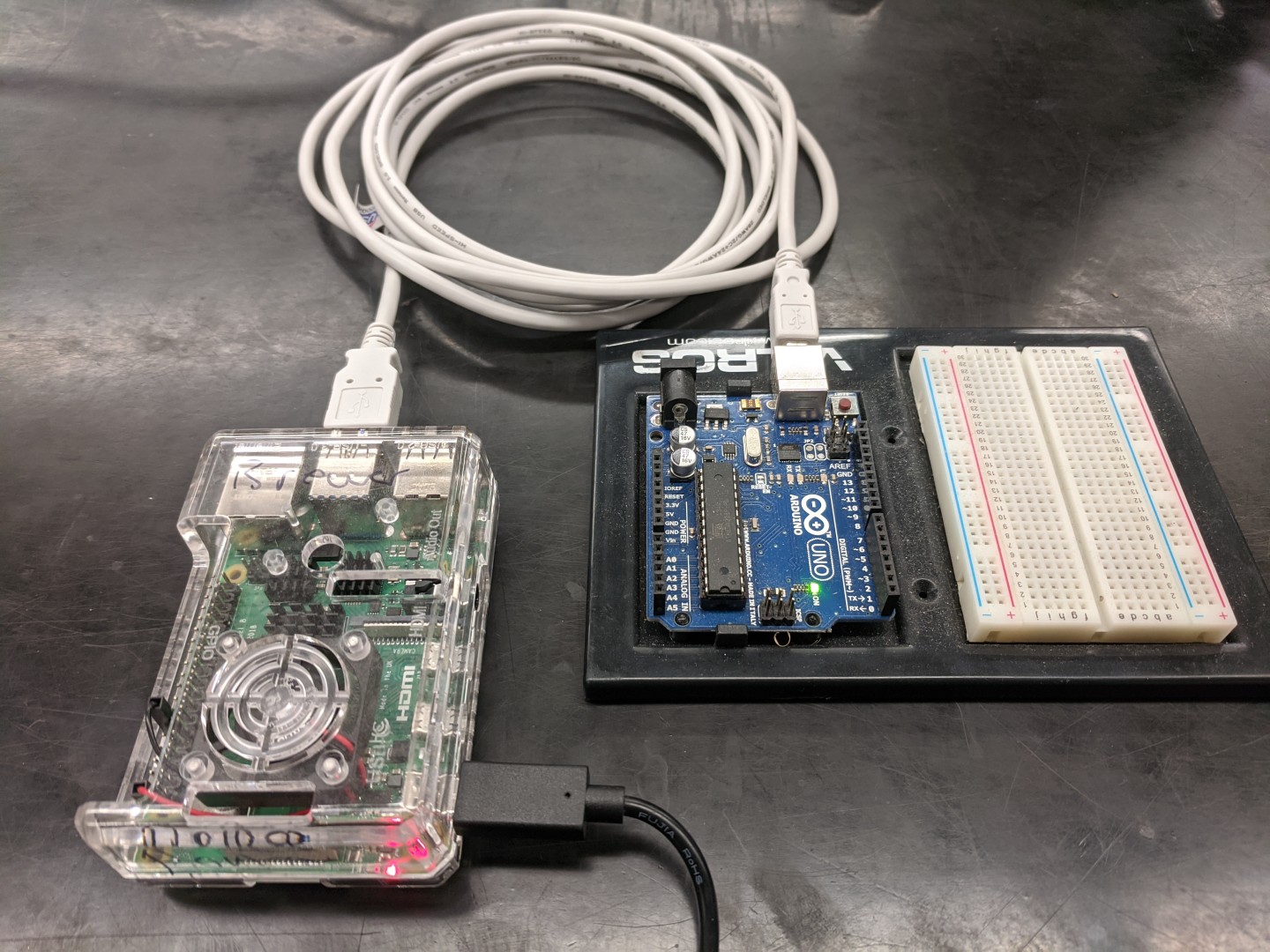
The Arduino is a hardware platform that has an open specification that has been widely deployed for prototyping embedded computing and interfacing with sensors and devices. As with a model system in biology, the main advantage of using it is the vast library of existing resources you can draw from for building your project.
There are many many versions of Arduino devices that have been developed for particular applications, but this guide will assume you’re using an Arduino Uno, which is a basic device that works well for prototyping.

A program for an Arduino is called a “sketch” and is written in a subset of the C++ programming language.
Arduinos only do two things. When they start, they run a function called “setup” that is executed only once. Then they run a function called “loop” which runs over and over again forever. That’s it.
Along the sides of an Arduino are sockets that can be used to connect with little wires, or “jumpers”, to a breadboard. (Or directly to a component).
Important:
Although Arduinos are generally forgiving, it’s possible to damage the electronics by shorting connections among pins. Use guidance when making connections and double check everything before plugging things in.
You should connect your Arduino to your Raspberry Pi and notice that an LED is lit to show that it is powered. The rest of this guide will assume you have an Arduino attached to a Raspberry Pi via USB.
Key Points
Arduinos are very simple devices for physical computing.
Arduinos are at the center of a universe of resources for making projects.
Installing arduino-cli
Overview
Teaching: 20 min
Exercises: 0 minQuestions
How can you program an Arduino board?
Objectives
Install and configure arduino-cli.
Until recently, the best way to program an Arduino was to use an Integrated Development Environment (IDE). The IDE provides a graphical interface to write programs, compile them, and upload them to the Arduino.
More recently, a command-line application for programming Arduinos and similar devices has been developed. The arduino-cli project is hosted at github and includes documentation.
You can download an install script (written in bash) and pipe it directly to a script to install it.
$ curl -fsSL https://raw.githubusercontent.com/arduino/arduino-cli/master/install.sh | sh
This will install the program in the “bin” directory of your home directory.
When you install it, it make need to create the “bin” directory. If that directory didn’t exist when you logged in, your path will not include it. The easiest way to solve this problem is to log out and log back in.
You can check by running the “which” command:
$ which arduino-cli
which should show you where the program is installed.
If you run the program with no arguments:
$ arduino-cli
It should emit a “help” message that shows the available options and commands. We should be able to use the arduino-cli program to see the Arduino board you have connected to the Pi.
$ arduino-cli board list
Assuming it finds a board it recognizes, you should see the serial port it’s on, the name of the board, the Fully Qualified Board Name (FQBN), and the core.
Downloading missing tool builtin:ctags@5.8-arduino11...
builtin:ctags@5.8-arduino11 downloaded
Installing builtin:ctags@5.8-arduino11...
builtin:ctags@5.8-arduino11 installed
Downloading missing tool builtin:serial-discovery@1.0.0...
builtin:serial-discovery@1.0.0 downloaded
Installing builtin:serial-discovery@1.0.0...
builtin:serial-discovery@1.0.0 installed
Updating index: library_index.json downloaded
Updating index: package_index.json downloaded
Updating index: package_index.json.sig downloaded
Port         Type              Board Name  FQBN            Core
/dev/ttyACM0 Serial Port (USB) Arduino Uno arduino:avr:uno arduino:avr
/dev/ttyAMA0 Serial Port       Unknown
You may need to install the core. You can check which cores are installed:
$ arduino-cli core list
And then, if it’s not in the list, install the required core. (Note: Replace “[core]” with the one listed from the output above, e.g. “arduino:avr”)
$ arduino-cli core install [core]
If you’re using some other type of Arduino-like board, you may need to do additional configuration of the arduino-cli program.
Downloading packages...
arduino:avr-gcc@7.3.0-atmel3.6.1-arduino7 already downloaded
arduino:avrdude@6.3.0-arduino17 already downloaded
arduino:arduinoOTA@1.3.0 already downloaded
arduino:avr@1.8.3 already downloaded
Installing arduino:avr-gcc@7.3.0-atmel3.6.1-arduino7...
arduino:avr-gcc@7.3.0-atmel3.6.1-arduino7 installed
Installing arduino:avrdude@6.3.0-arduino17...
arduino:avrdude@6.3.0-arduino17 installed
Installing arduino:arduinoOTA@1.3.0...
arduino:arduinoOTA@1.3.0 installed
Installing arduino:avr@1.8.3...
Configuring platform...
arduino:avr@1.8.3 installed
$ arduino-cli config init
This command will save a “arduino-cli.yaml” file inside an invisible “.arduino15 directory inside your home directory. This file includes a place where you can specify additional URLs for the “board manager” that will ensure the Arduino can recognize and download the necessary core to work with your particular board.
Key Points
There are graphical and command-line packages to program Arduinos
Arduino software uses a serial connection to program the device.
First Sketch
Overview
Teaching: 20 min
Exercises: 10 minQuestions
How do you program the Arduino?
What is the structure of an Arduino program?
Objectives
Install software for programming the Arduino.
Explore the structure of a ‘sketch’ or Arduino program.
Configure the settings necessary to program an Arduino.
The classic “hello world” program in the Arduino world is “blink”.
This command will create a new sketch:
$ arduino-cli sketch new blink
This creates a directory named “blink” and a file inside named “blink.ino” which contains the program. Go into directory (i.e. “cd blink”) and then edit the blink.ino file. The file will already contain “setup” and “loop functions” but you can delete everything and replace with this:
void setup() {
  pinMode(LED_BUILTIN, OUTPUT);
}

void loop() {
  digitalWrite(LED_BUILTIN, HIGH);
  delay(500);
  digitalWrite(LED_BUILTIN, LOW);
  delay(500);
}
Case Sensitive:
Using arduino-cli, programs are case-sensitive. On some platforms, computer programs are not case sensitive: it doesn’t matter whether letters are capital or lower case. But using arduino-cli, case matters.
Once you’ve saved the sketch, you can try to compile the program. Note that to compile, you need to specify the board you identified in the previous section.
$ arduino-cli -b=arduino:avr:uno compile
You should get a message with info about how much memory the sketch will require. Or an error message with information for debugging the problem.
Once you successfully compile the program, you can upload it to the Arduino. As above, you need to also identify the serial port where the board is connected.
$ arduino-cli -b arduino:avr:uno -p /dev/ttyACM0 upload
Working efficiently:
If you have to type out these entire commands each time you do anything, it would be a lot of effort. Luckily you can use the shell history to reuse commands. It’s perhaps useful to open two terminal windows: one where you are editing your sketch and another where you compile and upload the sketch.
You can also create aliases that make short versions of the commands to save keystrokes. You can add these to a .bash_aliases files.
alias compile='arduino-cli -b=arduino:avr:uno compile'
alias upload='arduino-cli -b arduino:avr:uno -p /dev/ttyACM0 upload'
While uploading, you should see the LEDs on the Arduino blink rapidly for a moment and then one LED will begin to blink regularly.
Questions
How long is the LED on? How long is it off. What are the units?
By changing the delays, you can vary how long the LED is on or off.
Try This
Try programming a pattern, like S-O-S in Morse code (“. . . — — — . . .”). Consider using a “for” loop to simplify coding.
Key Points
Arduino programs are called ‘sketches’ with a program file inside a directory.
Arduino programs have two functions: a ‘setup’ function that is run once, and a ‘loop’ function that runs forever.
Using the Breadboard
Overview
Teaching: 30 min
Exercises: 10 minQuestions
What is a breadboard?
How are a breadboard’s conductors organized?
How can you use a breadboard to connect devices to the Arduino?
Objectives
Understand how sockets are connected on a breadboard.
Understand how to program pins on an Arduino for OUTPUT.
Use Pulse Width Modulation to simulate an analog OUTPUT.
Let’s go back to the blink program we started with – or you can continue with the sketch as you modified in the previous episode.
Code Reuse:
Get used to starting with working code and adapting it to new purposes. It’s much easier to begin with something that does part of what you want and simply revising or extending it to do what you want.
You can either create a new sketch, but you can also go the parent directory that contains the folder with your blink sketch and copy the whole directory. Then rename the sketch inside to match the new name.
$ cd ..
$ cp -r blink blink-two
$ cd blink-two
$ mv blink.ino blink-two.ino
If you compile and upload the new sketch, the built-in LED should blink according to the pattern of the previous sketch.
void setup() {
  pinMode(LED_BUILTIN, OUTPUT);
}

void loop() {
  digitalWrite(LED_BUILTIN, HIGH);
  delay(500);
  digitalWrite(LED_BUILTIN, LOW);
  delay(500);
}
Replace LED_BUILTIN in the sketch above with 13. The built-in LED on the board is wired to pin 13 on the Arduino. Note that the LED continues to blink after compiling and uploading the sketch.
Next we will attach an LED on the breadboard to pin 13.
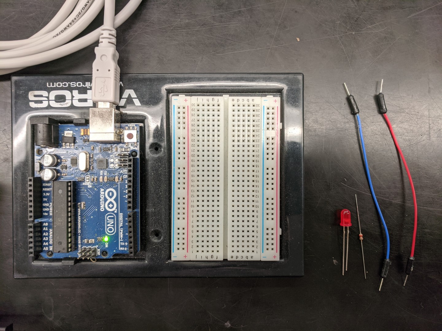
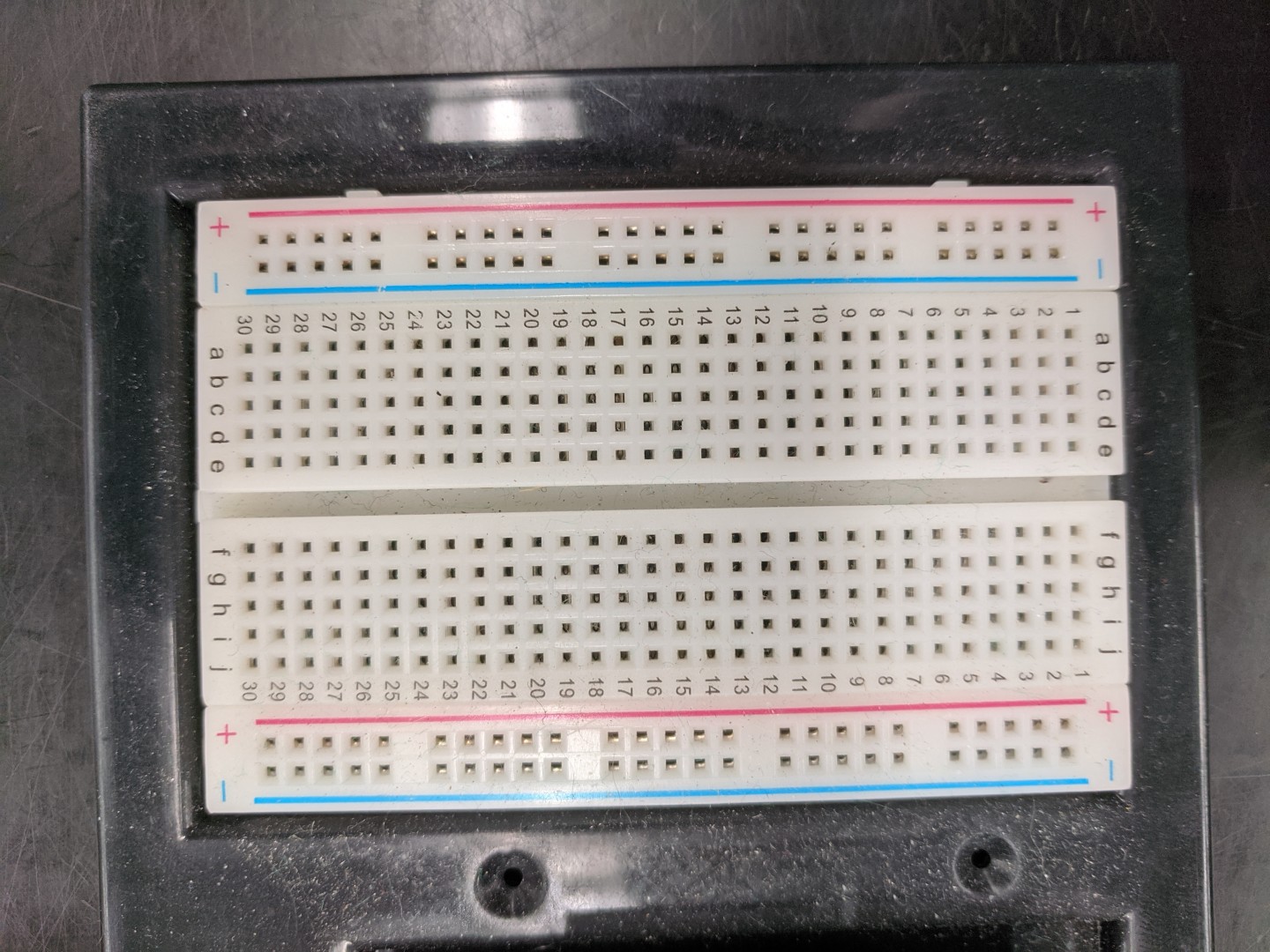
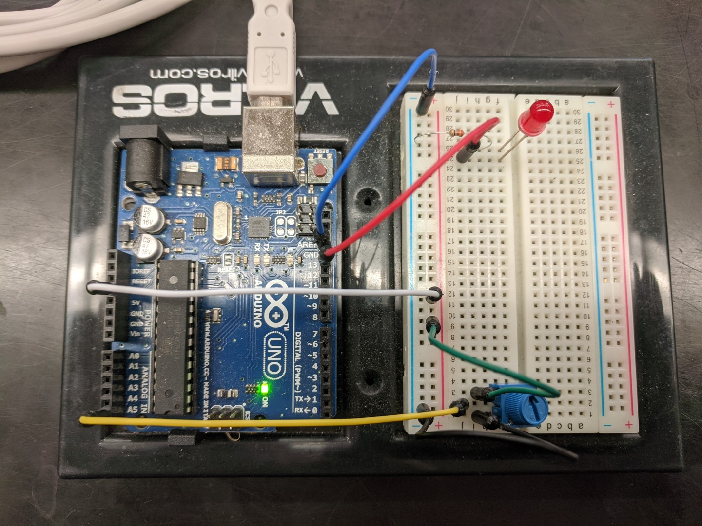
A breadboard has conductive elements that allow you connect components together using jumpers – small wires with connectors at each end. The typical breadboard that comes with an Arduino kit has two halves The red and blue lines represent conductors that run the length of the board. The other conductors run horizontally toward the middle, but don’t connect across the middle.
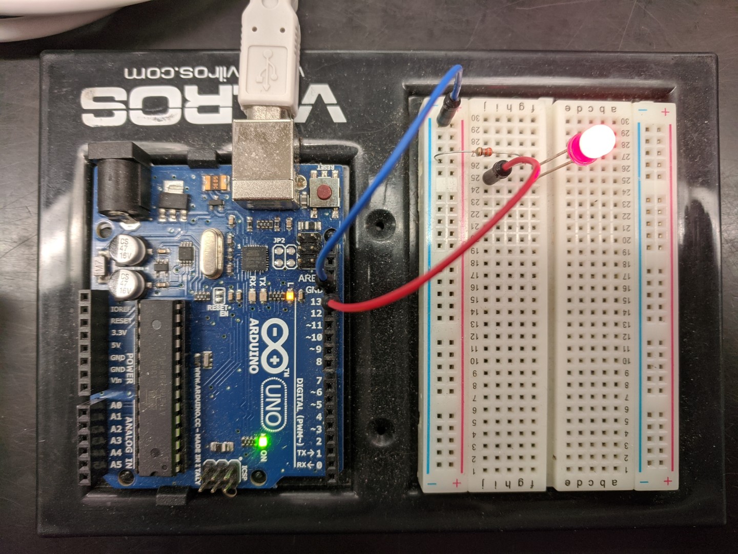
Place the LED so that its two connectors are attached to adjacent conductors on the breadboard (separate horizontal lines). Note that the two leads on the LED are different lengths. The longer lead is the one that should be connected to pin 13. Place a jumper from another socket on the breadboard and connect it to pin 13. But to complete the circuit, we need to connect the other lead to ground.
If you connect a jumper from one of the ground pins on the Arduino to the lengthwise conductor next to the blue line, we can use that to ground any of the circuits we build on the breadboard.
Finally, LEDs only need a tiny amount of electricity to light up and can be damaged by running too much electricity through them. For this reason, we will complete the circuit by using a resistor. In this case, we’ll use a 330ohm resistor. Put one end of the resistor in the same row of conductors as the short lead on the LED and the other end in the grounded conductor. If all of your connections are correct, the LED on the breadboard should blink at the same time as the built-in LED.
For portability, you can define a variable you can set to represent the pin you’re using to light the LED. Then you only need to one change to switch to a different pin.
Try this:
Try moving the positive connection to the LED to pin 6 and define a variable to represent that pin in all of the places where it is referenced.
Digital pins (and LEDS) are either off or on, but some digital pins (e.g. 3, 5, 6, 9, 10 and 11) can simulate analog OUTPUT through pulse width modulation (PWM): that is, they can rapidly turn on and off so that the proportion of the time the pin is HIGH can be varied.
int led=6;
void setup() {
  pinMode(led, OUTPUT);
}

void loop() {
  // gradually increase time pin is HIGH
  for(int i=0; i<255; i++){
    analogWrite(led, i);
    delay(5);
  }
  // gradually decrease time pin is HIGH
  for(int i=255; i>0; i--){
    analogWrite(led, i);
    delay(5);
  }
}
Try this:
Try moving the positive connection to the LED to pin 6 and define a variable to represent that pin in all of the places where it is referenced.
Key Points
Breadboards allow for complex, temporary connections.
Pins can be turned ON or OFF.
Pulse Width Modulation turns pins on and off really fast.
Using Digital and Analog Pins
Overview
Teaching: 30 min
Exercises: 10 minQuestions
How can the Arduino receive input via pins?
Objectives
Digital pins can be configured digital output or input.
Only analog pins can be configured analog input.
In addition to using pins for output, they can also detect input. Digital pins (0-13), like with output, can only detect HIGH or LOW.
int led=6;
// attach a wire to pin 3
int wire=3;
void setup() {
  pinMode(led, OUTPUT);
  // configure the pin for INPUT
  pinMode(wire, INPUT);
}

void loop() {
  // the pin reads HIGH, blink the LED.
  if (digitalRead(wire)) {
    digitalWrite(led, HIGH);
    delay(500);
    digitalWrite(led, LOW);
    delay(500);
  }
}
Try this:
Connect the jumper in pin 3 to ground. Then connect to 3.3v (the red conductor on the breadboard or one of the 3.3v pins on the Arduino.) What happens if you don’t plug anything into pin 3?
The Arduino Uno includes 6 pins that can accept “analog” input. These pins can measure the resistance between the pin and ground, perform an “analog to digital” conversion, and will output an integer value between 0 and 1023. Many sensors work using this principal but we can start by using a potentiometer.

A potentiometer is a device that changes resistance depending on how it’s adjusted. It has three pins. The middle pin should be connected to the analog
The analog pins are designated with a letter A (A0-A5) and are found on the opposite side of the Arduino from the digital pins. Connect A5 to the middle pin of the potentiometer.
Connect one side of the potentiometer to ground and the other side to 3.3V. (Note: it’s not a bad idea to do this two jumpers: one to the red conductor running the length of the breadboard and another between the red conductor and the side of the potentiometer).
This sketch is just the blink-two sketch from before, with a variable standing in for the LED pin and another variable (pot) defined to receive the value from the analog pin.
int led = 6;
void setup() {
 pinMode(led, OUTPUT);
}

void loop() {
  int pot;
  digitalWrite(led, HIGH);
  pot = analogRead(A5);
  delay(pot);
  digitalWrite(led, LOW);
  delay(pot);
}
Why is one variable (led) defined above the setup function and another (pot) defined inside the loop function?
Try this:
What do you think will happen if you reverse which side is ground and which side is power? Make a prediction and try it out.
Key Points
Digital pins are either HIGH or LOW while analog pins reflect a range from 0-1023.
Using Serial Connections
Overview
Teaching: 30 min
Exercises: 10 minQuestions
How can Arduino programs use the serial interace?
Objectives
Receive data from the Arduino.
Send data to the Arduino.
The Arduino uses a serial connection to receive the uploaded programs from the Raspberry Pi. But it can also exchange data via the serial connection while programs are running. The basic serial functions are well documented.
The serial connection is bi-directional, so you can both receive data from the Arduino and send information to it. By adding just a couple of lines, we can see what the potentiometer is actually set to.
int led = 6;
void setup() {
 pinMode(led, OUTPUT);
 // This turns on the serial connection
 Serial.begin(9600);
}

void loop() {
  int pot;
  digitalWrite(led, HIGH);
  pot = analogRead(A5);
  // this prints a line with the potentiometer reading
  Serial.println(pot);
  delay(pot);
  digitalWrite(led, LOW);
  delay(pot);
}
To see the readings on the Pi, we can use the “screen” command which can communicate via the serial ports.
$ screen /dev/ttyACM0 9600
You should see a series of values received. As long as “screen” has the serial port open, arduino-cli won’t be able to upload, so once you’re done looking at the connection, you need to shut down screen.
Discussion Questions
How variable are the readings? What is the full range of the potentiometer?
Everything you type, gets sent to the Arduino, with one exception: when you type Ctrl+A (while pressing the control key, type “a”), screen will listen for you to type a command. A backslash (\) will get screen to ask you if you want to” “Really quit and kill all your windows [y/n]”. Press Y to close the connection.
A useful way to send data is as “comma separated values”. An easy way to format the output is to use the “Serial.print” command to output individual elements on the line (values or commas) and then use “Serial.println” for the last element, which will send the line ending.
int led = 6;
void setup() {
 pinMode(led, OUTPUT);
 // This turns on the serial connection
 Serial.begin(9600);
}

void loop() {
  int pot;
  digitalWrite(led, HIGH);
  pot = analogRead(A5);
  // The Serial.print command doesn't issue a new line
  Serial.print(pot);
  delay(pot);
  // so we can print a comma
  Serial.print(",");
  // then make a new reading
  pot = analogRead(A5);
  // And print another value with a newline
  Serial.println(pot);
  digitalWrite(led, LOW);
  delay(pot);
}
You should now see pairs of values. If you rotate the potentiometer between readings, you should see the two values change independently.
int led = 6;
void setup() {
 pinMode(led, OUTPUT);
 // This turns on the serial connection
 Serial.begin(9600);
}

void loop() {
  int pot;
  digitalWrite(led, HIGH);
  pot = analogRead(A5);
  // The Serial.print command doesn't issue a new line
  Serial.print(pot);
  delay(pot);
  // so we can print a comma
  Serial.print(",");
  // then make a new reading
  pot = analogRead(A5);
  // And print another value with a newline
  Serial.println(pot);
  digitalWrite(led, LOW);
  delay(pot);
}
The Arduino Serial library can read data submitted byte-by-byte, one character at a time, but it also includes functions that watch for integers or floating-point values. We can use one to control how many times to blink.
int led = 6;
void setup() {
 pinMode(led, OUTPUT);
 Serial.begin(9600);
}

void loop() {
  int times = 0;
  // This waits until it receives an integer via the serial connection
  times = Serial.parseInt();
  // this loops the number of times entered.
  for (int i=0;i < times; i++) {
    int pot = analogRead(A5);
    digitalWrite(led, HIGH);
    Serial.print(pot);
    delay(pot);
    Serial.print(",");
    pot = analogRead(A5);
    Serial.println(pot);
    digitalWrite(led, LOW);
    delay(pot);
  }
}
Try this:
Can you add code to output an message telling the user to input the number of times to loop?
Key Points
A serial connection is birectional.
Serial connections exchange individual bytes.
Higher-level functions can help parse serial input.
Using Arduino Libraries
Overview
Teaching: 20 min
Exercises: 10 minQuestions
How can Arduino programming be extended?
Objectives
Don’t re-invent the wheel.
The Arduino programming language provides a lot of basic, low-level functionality, but there are many libraries that can provide higher-level functions that can simplify interacting with specialized hardware or information.
It’s feasible to search for libraries using arduino-cli directly
$ arduino-cli lib search [keyword]
But you can also browse the libraries to more readily see what’s available.
When you’ve identified a library you want to use, you can install it from the command line:
$ arduino-cli lib install [name_of_library]
When programming, you reference a library you want to use with an “#include” statement in your code, and then use the defined elements it provides. In this example, we’re using the TimedBlink library, which keeps track of when a pin should be turned on and off.
// include the library
#include <TimedBlink.h>
int led=6;

TimedBlink monitor(led);

void setup() {
  pinMode(led, OUTPUT);
  // Configure the function with times to stay on and off
  monitor.blink(500,500);
}

void loop() {
  // call frequently to blink at scheduled times.
  monitor.blink();
}
If you try to compile without installing the library, compilation will fail. Install the library and compile again.
Question
Why might this function be useful? How you imagine the function is operationalized? Are there any limitations to this approach?
Finally, under some circumstances, you might want to create a library of your own.
Key Points
Libraries can provide additional functionality, especially for hardware, but also for functionality.
Using git for Arduino programs
Overview
Teaching: 20 min
Exercises: 10 minQuestions
How can I maintain Arduino programs with git?
How can I create a github reposistory from the command line?
Objectives
Use git for version control with Arduino sketches.
You should consider using version control for any serious programming you do. Here is a quick set up steps to help you create a repo and maintain a repository with an Arduino program.
You should have an account at github, an ssh key, and have git configured on your raspberry pi. If you’ve gone through the Software Carpentry Version Control with Git you should have already set up most of these.
You can check your ssh keys by listing the contents of your .ssh directory
$ ls -al ~/.ssh
If you don’t have an id_rsa.pub file listed, you can create one:
$ ssh-keygen
Follow along with the prompts and leave the password blank.
To configure github to use your public key, you can list out the key:
$ cat ~/.ssh/id_rsa.pub
Then select and copy the contents of the key, visit your GitHub settings page, click New SSH key, and past the key into the field. (You also have to give the key a title – you can use the hostname of your pi.)
Finally, test the configuration:
$ ssh -T git@github.com
You can check your git configuration with git config:
$ git config -l
If your user.email and user.name are not set, you can set them:
$ git config --global user.email "you@example.com"
$ git config --global user.name "Your Name"
$ git config --global init.defaultBranch main
If you haven’t installed hub, you need that first.
$ sudo apt-get install hub
Create a directory Once the repository exists you can push changes to the repository online. Here are a series of commands that assume you have an ssh key set up with github.
$ mkdir projectname
$ cd projectname
$ touch README.md
$ git init
$ git add *
$ git commit -m "First commit."
With hub you can interact with github and easily create a new repository:
$ hub create
Or you should be be able to. Unfortunately, you currently may need to create a “personal access token” for hub via Settings -> Developer Settings -> Personal Access Tokens. Once you create a token, you can copy it and then paste it in where you get asked for a password.
You should now be able to push your changes to github.
$ git remote add origin git@github.com:USERNAME/projectname.git
$ git push -u origin main
For some Arduino programs, you may need to “add” other files, but avoid including the compiled files (.elf and .hex). Create a “.gitignore” file (e.g. “nano .gitignore”) an insert these patterns to avoid adding them by mistake.
*.elf
*.hex
Then you can use the following commands to push changes to your github repository.
$ git add *
$ git commit -m "informative message"
$ git push
Key Points
Maintain all your programming in version control.