Using Digital and Analog Pins
Overview
Teaching: 30 min
Exercises: 10 minQuestions
How can the Arduino receive input via pins?
Objectives
Digital pins can be configured digital output or input.
Only analog pins can be configured analog input.
In addition to using pins for output, they can also detect input. Digital pins (0-13), like with output, can only detect HIGH or LOW.
int led=6;
// attach a wire to pin 3
int wire=3;
void setup() {
  pinMode(led, OUTPUT);
  // configure the pin for INPUT
  pinMode(wire, INPUT);
}

void loop() {
  // the pin reads HIGH, blink the LED.
  if (digitalRead(wire)) {
    digitalWrite(led, HIGH);
    delay(500);
    digitalWrite(led, LOW);
    delay(500);
  }
}
Try this:
Connect the jumper in pin 3 to ground. Then connect to 3.3v (the red conductor on the breadboard or one of the 3.3v pins on the Arduino.) What happens if you don’t plug anything into pin 3?
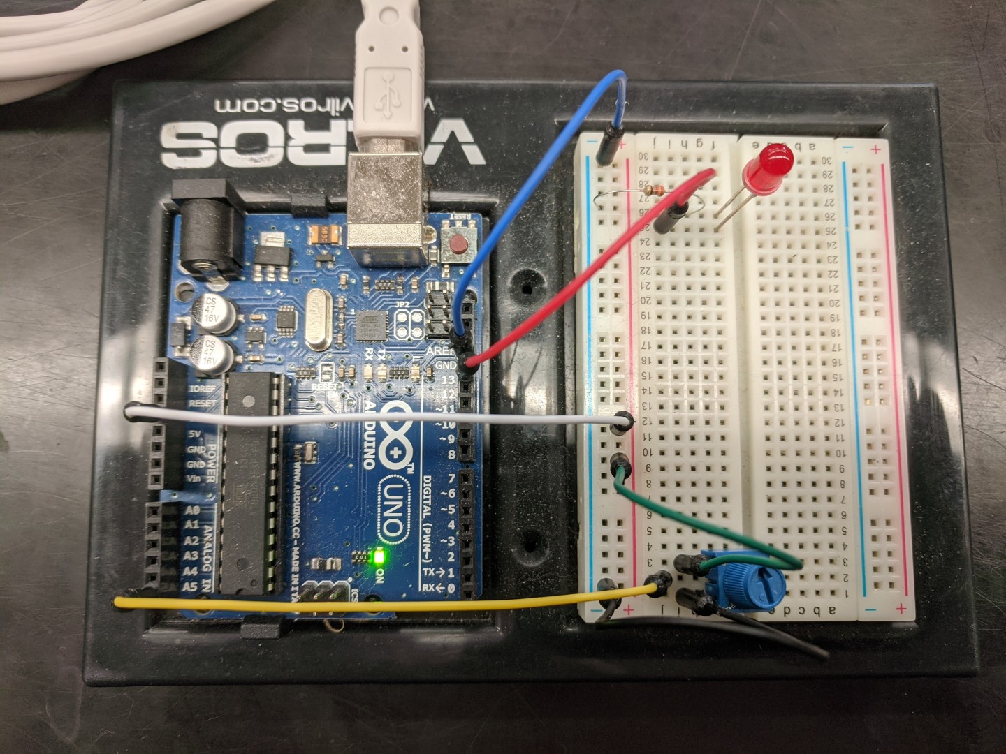
The Arduino Uno includes 6 pins that can accept “analog” input. These pins can measure the resistance between the pin and ground, perform an “analog to digital” conversion, and will output an integer value between 0 and 1023. Many sensors work using this principal but we can start by using a potentiometer.

A potentiometer is a device that changes resistance depending on how it’s adjusted. It has three pins. The middle pin should be connected to the analog
The analog pins are designated with a letter A (A0-A5) and are found on the opposite side of the Arduino from the digital pins. Connect A5 to the middle pin of the potentiometer.
Connect one side of the potentiometer to ground and the other side to 3.3V. (Note: it’s not a bad idea to do this two jumpers: one to the red conductor running the length of the breadboard and another between the red conductor and the side of the potentiometer).
This sketch is just the blink-two sketch from before, with a variable standing in for the LED pin and another variable (pot) defined to receive the value from the analog pin.
int led = 6;
void setup() {
 pinMode(led, OUTPUT);
}

void loop() {
  int pot;
  digitalWrite(led, HIGH);
  pot = analogRead(A5);
  delay(pot);
  digitalWrite(led, LOW);
  delay(pot);
}
Why is one variable (led) defined above the setup function and another (pot) defined inside the loop function?
Try this:
What do you think will happen if you reverse which side is ground and which side is power? Make a prediction and try it out.
Key Points
Digital pins are either HIGH or LOW while analog pins reflect a range from 0-1023.