Pinout
Overview
Teaching: 20 min
Exercises: 0 minQuestions
What pins are available?
What do pins do?
How can you refer to pins?
Objectives
Refer to pins physically and programmatically
There are 40 GPIO pins. A great resource for exploring the pins is the Pinout Comprehensive Guide to the Raspberry Pi.
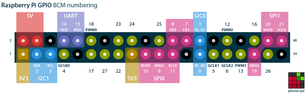 via [pinout.xyz](https://pinout.xyz/)
The pins have two numbering schemes. The BOARD numbering scheme refers to the physical location on the board. The BCM scheme refers to the underlying software representation.
Recommendation:
When referring to connections of physical pins, use the BOARD specification. When calling out pins in software, use the BCM scheme.
Some pins have permanently assigned functions. Ground pins are always ground pins. There are pins that provide 5v and 3.3v – always.
Some pins are digital pins with no additional functionality: they can be set to either input or output without concern that using them might impact other functions that might be needed in the future.
Some pins are defined for use with serial protocols. These protocols can be enabled by running raspi-config which adds lines to /boot/config.txt that the kernel consults when the system boots and uses to load a kernel module that expects to use specific pins. Each protocol will expect particular pins to serve specific functions. It’s fine to use these pins for other purposes if a particular serial protocol isn’t going to be needed.
For our first examples, let’s hook up an LED to Pin 11 (That’s the BOARD numbering scheme – it will be GPIO 17 using the BCM scheme.)
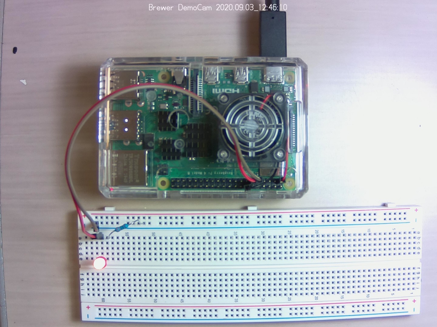
Two female to male connectors are used to connect between the GPIO pins and the breadboard. The connection to ground is connected to one of the bus strips (the lengthwise ground conductor). The GPIO 17 is connected to one of the terminal strips. The LED is connected with the long conductor attached to GPIO 17. The shorter conductor is bridged to ground with a 330mv resistor so that it doesn’t draw too much power from the Pi.
Key Points
There are 2 separate schemes, BOARD and GBM, for referring to the pins.