Introduction
Overview
Teaching: 10 min
Exercises: 0 minQuestions
How can Raspberry Pi interact with other devices?
Objectives
Raspberry Pi can interact via many different interfaces
The Raspberry Pi comes with a large array of connectors to interact with other devices. Some of these are tied to very specific forms of input/output (think ethernet, usb, hdmi, camera, etc.) Along one side of the board, however, is a set of pins that are available for “general purpose input/output” or GPIO.
Some of these have specific purposes. Four provide power (two at 3.3v and two at 5v). Eight are “ground” connections to complete a circuit from any of the other pins. Some are pre-configured to be used for several kinds of serial connections (i.e. UART, SPI, & I2C). With raspi-config, you can configure the Pi to turn on this functionality.
The other pins are undefined and can be easily used for either input or output. In both cases, these are boolean (true or false) operations. For input, they can detect HIGH or LOW and for output, they can be set to be HIGH or LOW.
Important:
When a GPIO pin is set HIGH, it provides enough power to be detected, but isn’t designed to actually power much more than an LED. If you connect a device that draws too much power, its possible to damage the circuitry of the Raspberry Pi. Be cautious and make sure to use resistors to ensure the safety of your Pi.
This means that the Raspberry Pi has no “analog” pins, like the Arduino. The GPIO can be used to detect on/off events, like switches. Or receive data via a serial connection. But to convert a voltage into a digital signal, you need to use another device, like an Analog-to-Digital converter. Or an Arduino.
Key Points
Raspberry Pi supports many means of connecting to other devices.
The GPIO offers digital pins that can be configured for many purposes.
The Raspberry Pi does not have analog pins like an Arduino.
Permissions
Overview
Teaching: 20 min
Exercises: 0 minQuestions
What Unix permissions are needed to interact with the GPIO?
How should permissions be structured for production versus development?
Objectives
Inspect
The interface between the hardware and software of the Raspberry Pi is the linux kernel. The kernel builds a file system located at /sys that includes entries that represent all of the physical hardware that the kernel “knows” about. The entries for the GPIO are in /sys/class/gpio.
In early versions of Raspbian, the GPIO could only be accessed by root initially and a series of steps were necessary to assign the GPIO devices permissions that allowed ordinary users to access them. With newer versions of Raspbian, this is not necessary. By default the GPIO devices can be controlled by anyone in the “gpio” unix group. If you have problems with permissions, check to make sure you’re in the gpio group and add your account to the group if necessary.
Group memberships appear in /etc/group and you can use grep to do pattern matching:
$ grep gpio /etc/group
gpio:x:997:pi
The first field is the name of the group and the last field can be a comma-delimited list of usernames that are in the group.
There are a number of other groups that might be relevant to any particular project you want to work on. As long as you’re using the “pi” account, you should already be in all of the important groups:
$ grep pi /etc/group
adm:x:4:pi
dialout:x:20:pi
cdrom:x:24:pi
sudo:x:27:pi
audio:x:29:pi
video:x:44:pi
plugdev:x:46:pi
games:x:60:pi
users:x:100:pi
input:x:105:pi
netdev:x:109:pi
pi:x:1000:
spi:x:999:pi
i2c:x:998:pi
gpio:x:997:pi
For development purposes, using the “pi” account is convenient. For security purposes, a finished device would use an alternate username and put that account only in the groups necessary for it to accomplish its tasks. You can change group memberships by editing the file. Or you can add a username to a group using the command below.
$ sudo usermod -a -G groupname username
Key Points
First key point. Brief Answer to questions. (FIXME)
Pinout
Overview
Teaching: 20 min
Exercises: 0 minQuestions
What pins are available?
What do pins do?
How can you refer to pins?
Objectives
Refer to pins physically and programmatically
There are 40 GPIO pins. A great resource for exploring the pins is the Pinout Comprehensive Guide to the Raspberry Pi.
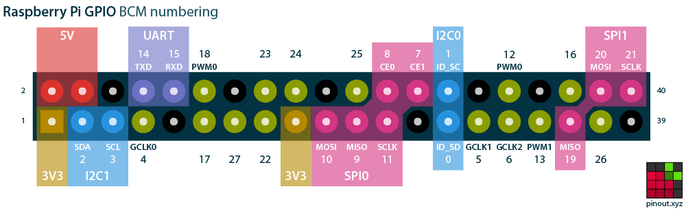 via [pinout.xyz](https://pinout.xyz/)
The pins have two numbering schemes. The BOARD numbering scheme refers to the physical location on the board. The BCM scheme refers to the underlying software representation.
Recommendation:
When referring to connections of physical pins, use the BOARD specification. When calling out pins in software, use the BCM scheme.
Some pins have permanently assigned functions. Ground pins are always ground pins. There are pins that provide 5v and 3.3v – always.
Some pins are digital pins with no additional functionality: they can be set to either input or output without concern that using them might impact other functions that might be needed in the future.
Some pins are defined for use with serial protocols. These protocols can be enabled by running raspi-config which adds lines to /boot/config.txt that the kernel consults when the system boots and uses to load a kernel module that expects to use specific pins. Each protocol will expect particular pins to serve specific functions. It’s fine to use these pins for other purposes if a particular serial protocol isn’t going to be needed.
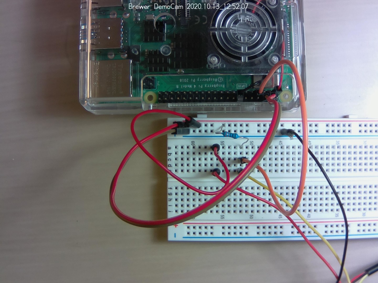
For our first examples, let’s hook up an LED to Pin 11 (That’s the BOARD numbering scheme – it will be GPIO 17 using the BCM scheme.)
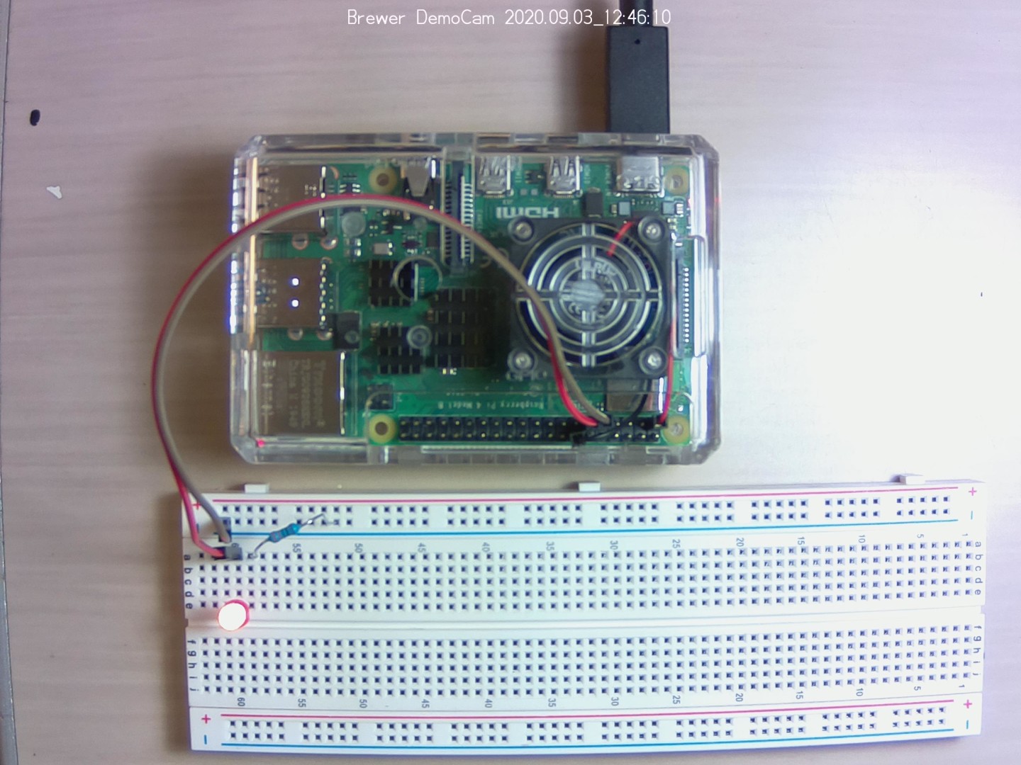
Two female to male connectors are used to connect between the GPIO pins and the breadboard. The connection to ground is connected to one of the bus strips (the lengthwise ground conductor). The GPIO 17 is connected to one of the terminal strips. The LED is connected with the long conductor attached to GPIO 17. The shorter conductor is bridged to ground with a 330mv resistor so that it doesn’t draw too much power from the Pi.
Key Points
There are 2 separate schemes, BOARD and GBM, for referring to the pins.
GPIO via Bash
Overview
Teaching: 30 min
Exercises: 20 minQuestions
How can you interact with the GPIO?
What do pins do?
How can you refer to pins?
Objectives
Understand relationship between the physical (pins) and virtual (file-system)
It is possible to access the GPIO directly via the command line using bash commands to configure and manipulate the devices directly via the linux kernel.
This command will make the pin available to userspace for programming:
$ echo "17" > /sys/class/gpio/export
This command will set whether the pin should be for input or output:
$ echo "out" > /sys/class/gpio/gpio17/direction
This command will set the pin to “HIGH.”
$ echo "1" > /sys/class/gpio/gpio17/value
And this sets it back to “LOW.”
$ echo "0" > /sys/class/gpio/gpio17/value
And this sets it back to “LOW.”
$ echo "17" > /sys/class/gpio/unexport
The capabilities are limited, however, and not all of the functionality is available using these low-level tools. There is more complete documentation
There are higher-level libraries that offer more robust ways to interact with the GPIO that we’ll be studying next. But it’s worth being aware of how the system is put together at the lowest level.
WARNING! raspi-gpio set writes directly to the GPIO control registers ignoring whatever else may be using them (such as Linux drivers) - it is designed as a debug tool, only use it if you know what you are doing and at your own risk!
The raspi-gpio tool was designed to help hack/debug BCM283x GPIO. Running raspi-gpio with the help argument prints an informative help message. raspi-gpio can get and print the state of a GPIO (or all GPIOs) and can be used to set the function, pulls and value of a GPIO. raspi-gpio must be run as root.
There are several high-level libraries for interacting with the GPIO. We’re going to use GPIO Zero for most purposes. But it’s worth understanding that it is built on top of a lower-level library RPI.GPIO. The higher level library abstracts a lot of the underlying complexity.
Let’s do “blink” again, but with the Raspberry Pi.
#! /usr/bin/env python3

from gpiozero import LED
from time import sleep

led = LED(17)

while True:
    led.on()
    sleep(1)
    led.off()
    sleep(1)
Note: you may need to install the GPIO Zero and/or RPi.GPIO libraries.
Key Points
GPIO elements appear in the Raspberry Pi file-system and can be easily inspected/modified.
Using GPIO Pins for Input
Overview
Teaching: 20 min
Exercises: 20 minQuestions
How can GPIO pins get information in?
Objectives
GPIO pins can detect change of state
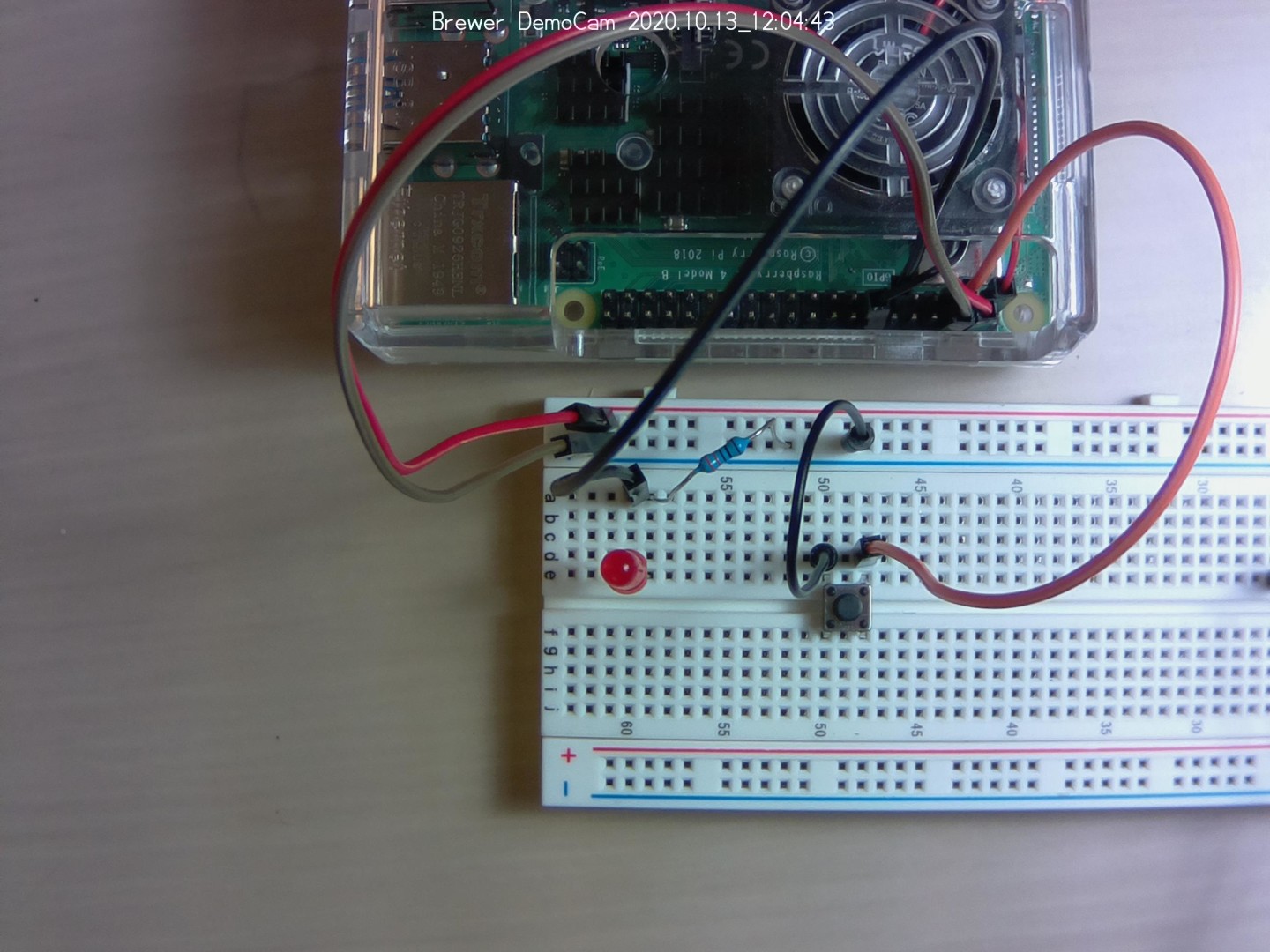
Just like with the Arduino, you can detect events using the digital pins on the Raspberry Pi. If you leave the LED wired to pin 17 and connect the button to pin 3, you can detect the button press and turn the LED on with the GPIO Zero library.
#! /usr/bin/env python3

from gpiozero import LED, Button
from signal import pause

led = LED(17)
button = Button(3)

button.when_pressed = led.on
button.when_released = led.off

pause()
In this example, the LED stays lit as long as the button is pressed. But you could just as easily have each button press turn it on or off. I fact…
Try this:
Modify the program to turn the LED with one button press and turn it off with another. Extra credit for checking state (to make sure its off before turning it on.)
Some analog devices come with a “digital pin” that works with a threshold, meaning that if the value being measured exceeds some target, the pin turns on. Sometimes this is sufficient, e.g. an alarm. Or a trigger. For actually collecting analog data, however, you would need to use an analog-to-digital converter. Or select a sensor that communicates over a serial interface.
Key Points
The GPIO only has digital pins.
Using GPIO Pins for Output
Overview
Teaching: 20 min
Exercises: 20 minQuestions
How can you use pins to control things?
Objectives
Learn how to control digital pins via python.
If you can turn a digital pin, you can use that as a signal to turn on other devices. You should generally not try to power devices (beyond an LED) using the digital pins, which you should use for signaling.
For low power devices, like small stepper motors or servos, you can deploy a transistor or relay that can use use an electrical signal to open or close a switch to a power source.
A typical transistor has three elements the positive side, connected to the electrical source, a negative side, than will be connected in series with the element to be powered, and the middle, or “logic” pin, that is connected to what will send the signal – ie, one of the programmable data pins on the raspberry pi.
Try this:
Use pin 17 to control a transistor to power the LED from the blink.py program from the previous episode.
If you need more power than the transistor can handle, you can use the transistor to control a relay which works much the same way, but that has an electro-mechanical switch inside: you control the transistor that energizes a magnet which controls the switch.
If you’re planning to work with power from the “mains” (i.e. wall electrical power), the simplest and safest way is to use a device expressly designed for that purpose. Here’s an example of a device that can detect the change on a GPIO pin to turn electrical sockets on/off.
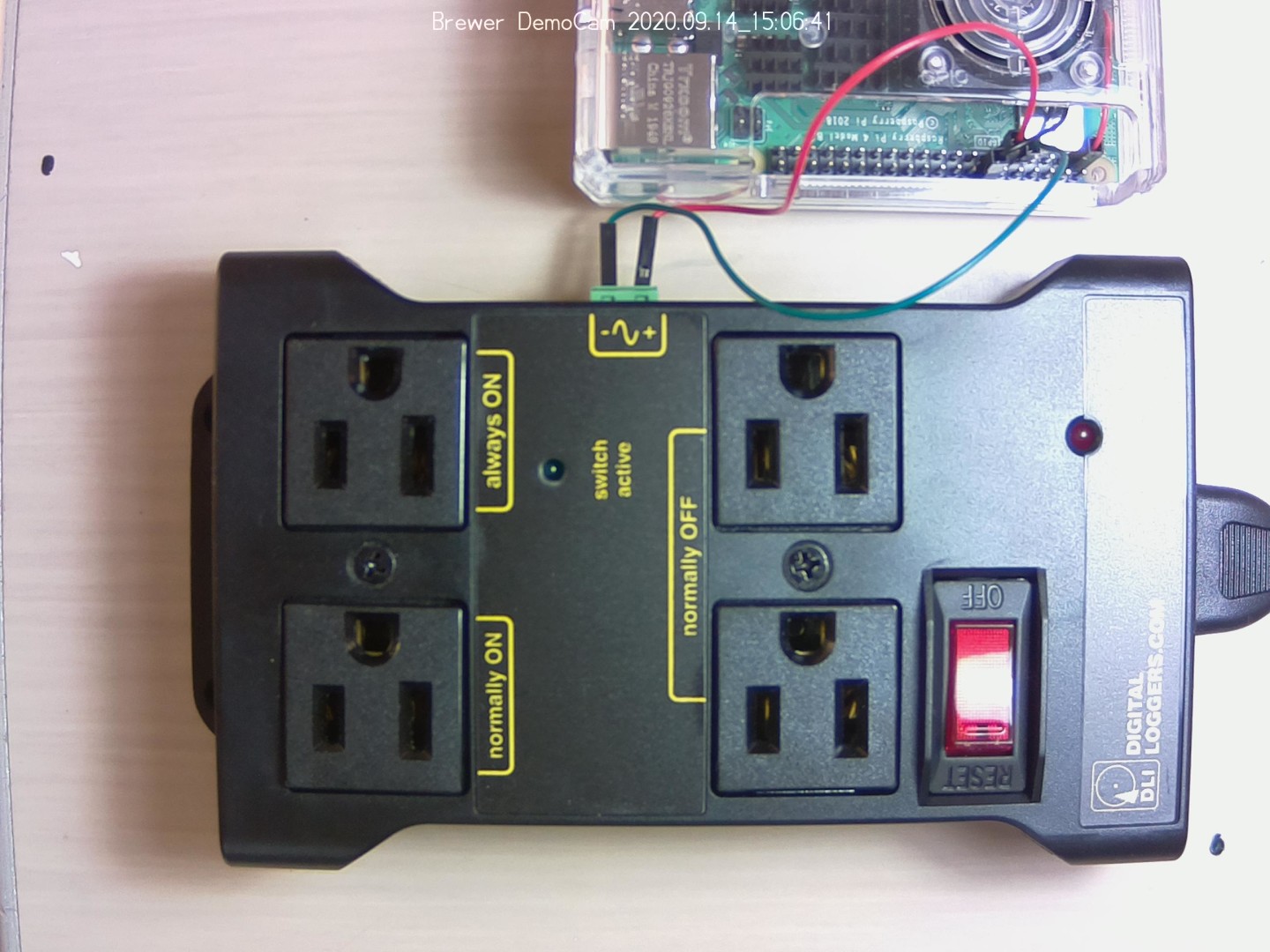
Devices like this carefully isolate the circuitry energized with the mains electricity. Don’t try to work with high voltages directly without expert assistance.
Key Points
You can signal with digital pins.
Don’t try to power things with digital pins.
GPIO for serial connections
Overview
Teaching: 30 min
Exercises: 30 minQuestions
What kinds of serial connections are there?
How do you enable serial connections?
Objectives
Turn on overlays for serial interfaces
Wire up the appropriate pins for serial connections
Use Python to receive and output data from a serial device
There is a universe of sensors and other devices that can talk over some kind of serial interface. There are several different serial interfaces supported by the Raspberry Pi (depending on exactly what you mean by “serial interface” and “supported”). This high level overview provides an introduction to the kinds of protocols that are supported.
This guide will focus on one of the simplest and most common. The others are similar in principle and vary mostly in the details of how they’re implemented.
1-wire
This example uses the DS18B20 thermometer which communicates over a 1-wire serial interface. This is a device which appears in a number of different form factors, including weatherproof, immersible devices.
To enable the 1-wire interface on the Raspberry Pi, you need to add (or uncomment) a line in /boot/config.txt:
dtoverlay=w1-gpio
After making this change, you need to reboot the Pi for the change to take effect.
If you want to know what these lines represent, you can read the Device Tree documentation but the short answer is that it tells the system how (or perhaps “which”) physical hardware should be represented in the file system so you can access it. In this case, it creates an entry in the file system so that data received via GPIO 4 will appear in a file somewhere below the /sys/bus/w1 directory.
You can connect 1-wire devices with three connections: power, ground, and data. But you also need a strong resistor (4.7kΩ or 10kΩ) to go between power and data to “pull up” the connection.
Once you have the thermometer connected, you should be able to look inside the /sys/bus/w1/devices directory and see the file-system entry for the thermometer. It will use a unique identifier that begins with “28”. Make a note of this identifier.
To see what data the thermometer is sending you can read the data directly by using cat:
cat /sys/bus/w1/devices/28-01191a3c12d5/w1_slave
30 01 4b 46 7f ff 0c 10 09 : crc=09 YES
30 01 4b 46 7f ff 0c 10 09 t=19000
The “t=” shows the temperature in Celsius times 1000.
The DS18B20 device is really amazing. Read the data sheet for more information about its full capabilities.
Here is a script in python that can read the data from the thermometer and output the values as a CSV file with a time stamp.
#! /usr/bin/env python3

import time

device = '/sys/bus/w1/devices/28-01191a3c12d5/w1_slave'
#    Unique Identifier --->   ^^^^^^^^^^^^^^^

try:
  while True:
    file = open(device, 'r')
    line = file.readlines()
    file.close()
    t = line[1].find('t=') # find position where 't=' is
    if t :
      temp_val = line[1][t+2:] # grab what's 2 characters after position
      temp_c = float(temp_val) / 1000.0
      timestamp = time.strftime("%Y-%m-%d %H:%M:%S", time.localtime())
      print(f'"{timestamp}",{temp_c}') #enclose timestamp (a string) in quotes
      time.sleep(1)
except:
  file.close() # make sure the file is closed
  print("done.")
This example uses a single device, but you can actually connect multiple devices at the same time that can even use the same pull-up resistor. This makes collecting multiple temperature readings (for example) very simple.
Key Points